Parts you need
- half a meter of enameled copper wire 0.3 mm (that is 0,0118110236")
- some tweezers
- magnifying glasses
- some fine pointed device like a scalpel
- a soldering iron with a fine fine fine tip
- a AMS1117 3.3V low dropout regulator (you get ten for a dollar on ebay)
- perhaps a hot air station
- perhaps some flux
The copper wire is not mission critical. There are two ways to get it done, so take what you have.
The solder iron tip I used was a Hakko T12-BL. With a Hakko FM-2028 handle and a self build base station. I love it.
For the AMS1117: just buy it on ebay. You will get the right one, because there is basically only one type on ebay. Just check the voltage.
Flux and hot air station is nice, makes the work a little easier and is an overall good addition to your workplace.
Note 1
The Funduino Nano V3.0 Lisa 2011 uses a different voltage regulator than the original Arduino.CC layout. So the PCB differs in several ways. It does not really help to look at the original PCB layout. I found nothing about the Funduino on the net beside that you can buy it and it is open source.
A lot of the cheap Nano clones on ebay seem to base on this layout.
Note 2
This is for those Nanos with FT232RL. It might not work for the CH340G ones, I didn’t look into that. (Send me ten of those and I will.)
Steps:
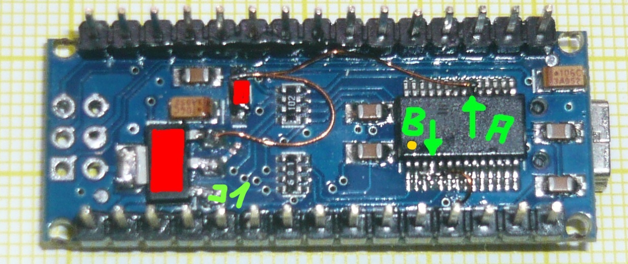
1. Remove the 5 V LDO regulator (big red).
2. Remove the Schottky diode (small red).
(The photo is a little bit missleading. I didn’t remove the diode but instead cut the track on the PCB. That was done because I put back the hot air before I noticed that I have to remove the diode, too. And I didn’t want to heat the PCB twice.)
I used about 350° C (662° F) air, flow at level 3, small hole blow thingy.
3. Add the 3.3 V LDO regulator
Just solder it at the old place.
4. Bend up pin 4 and pin 20 of the FT232RL chip
Look at the photo to identify the pins. It’s the 4th from the yellow dot and the 6th from the other side.
Be very very very very carefull. The pins are needed, don’t break them. This is a job where you want your kids in bed, wife looking netflix and cat locked in the basement. Take your time and patience.
It might be easier to desolder the FT232RL with a hot air gun and replace it with a new one with prebend pins. I didn’t try that, because I have no kids and cats.
5. Wire the supply voltages
(I used 350° C to remove enamel varnish from the ends of the copper wire. And 280° C/536° F to solder stuff on the PCB.)
A wire from the anode side of the now ex-diode goes to the pin 20 of the FT232RL. On the still ex-anode side is 5 V from USB, pin 20 is Vcc. So there the FT232RL gets its power from.
The second wire from the anode side goes to the pin 3 (input) of the AMS1117. The LDO get its supply voltage from there, its pin 2 (middle) is the output, pin 1 is ground.
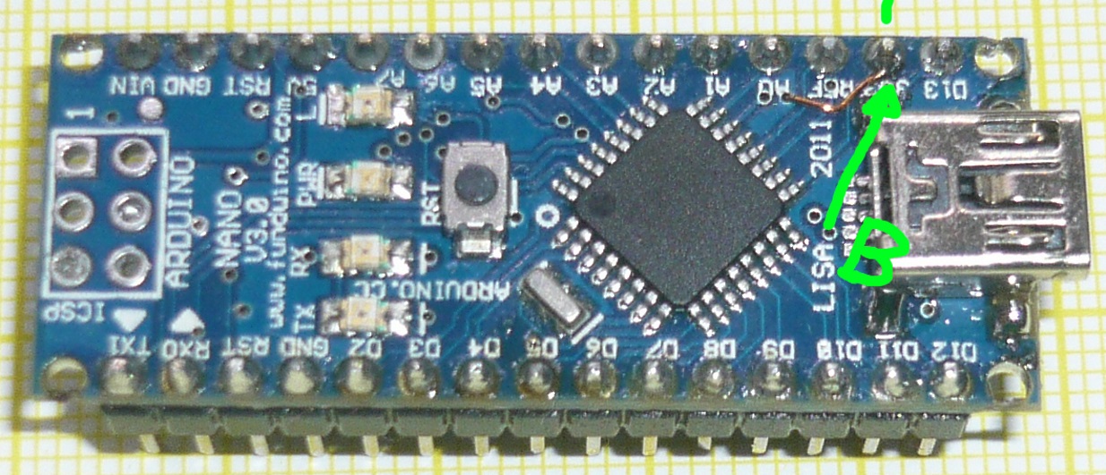
6. Wire the 3.3 FT232RL voltage
Pin 4 of the FT232RL must go to some 3.3 V source. I choosed the 3.3V pin of the Nano, that is coming from pin 17 of the FT232RL (solution I). Thinking about that solution it might have been easier to run the wire from pin 4 of the FT232RL to pin 2 of the AMS1117 (avoiding the through hole solution. Solution II.) Anyway, it works.
As far as I understood it, the VccIO (pin 4) voltage must be the same as the Atmegas serial side level. So a 5V-Atmega —> 5V VccIO, 3.3V-Atmega —> 3.3V VccIO.
Thats it
I will secure the wires with some hot snot glue.
Usage with USB only
On Vin you get 5 V from USB, on 3.3 you get weak 3.3V (solution I) or strong 3.3 V (solution II).
Usage without USB only
Feed 5V (not more!) into Vin.
Usage with USB and Vin connected
Dont’ do that. Or add a Schottky.
(Remark: I didn’t think very long about the last three statements, it is late and I’m tired. So it might be different. But mostly I’m not too far off.)